| DMX Splitter |
||||||||||||||
|
DMX Splitter = Yet another one! |
Docs |
||||||||||||
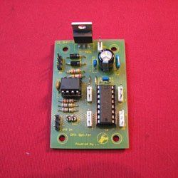
This year I added DMX controlled devices to my display and needed a simple DMX splitter to make the job of cabling the show a lot easier. Matt Edwards provided the original circuit idea, and I designed a PCB to make the job of building it a bit easier. Circuit Description The DMX splitter is a variation on a number of designs. The DMX IN is terminated on the OPTOCOUPLER (6N137) via a matching network (R1,2, 3 and LED). The OPTO provides galvanic isolation from the first DMX network to the others. ** Please note I have only isolated in INPUT from the grouped OUTPUTS. The OPTO is coupled to a Texas Instruments four way 485 transceiver (AM26LS31C). Each of the 485s is matched to and output connecter (CON3) There are a couple of options to power the board. you can use a centre tapped transfomer (12.6VCT) connected to X7, or bring in DC and connect to Pins 1 or 2 of X7 (Pos) and Pin 3 (Gnd). THe DC voltage needs to be greater than 8 V DC @ 200mA.You could obmit the 5V regulator, and bring in 5 V DC directly to X1. Cannon Socket pinouts - there are different types of connectors used for DMX, I generally use 3 or five pin XLR series. Extra information
Any questions, please contact me.
|
Schamatic Diagram
Board Layout
|
|||||||||||||